--
This is an overview of how I designed and built an electronic skateboard. This project was my final project for an electronics design class I took as part of my studies at Reykjavik Technical College in spring 2017.
SPECIFICATIONS
- 1820W BLDC Motor
- 25km+ range
- 222Wh Lithium Polymer Battery
- Reliable 433Mhz Communication
- Custom Controller
BILL OF MATERIALS
- ATTiny85 MCU 16Mhz
- Skywalker 80A U-BEC ESC
- STX-882 433Mhz Transmitter
- SRX-882 433Mhz Receiver
- 400KV 1820W BLDC Motor
- 2x 6S 22.2V 5000mAh Lithium Polymer Battery
- 3.7V 300mAh Lithium Polymer Battery
- USB Lithium Battery Charge Controller
- 4x XT-60 Connectors
- Custom PCB
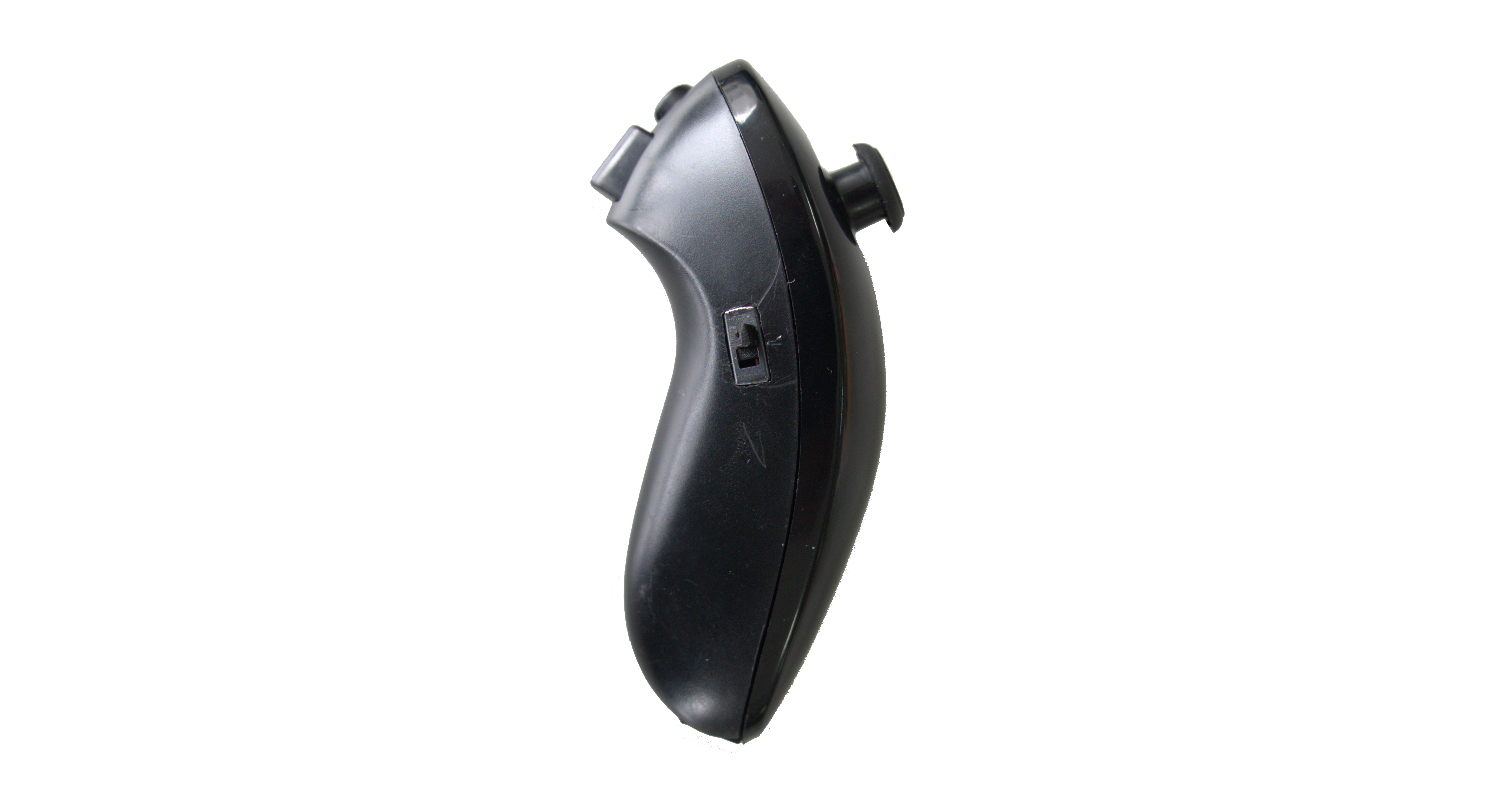
- Nintendo Wii Nunchuck
- Longboard Trucks
- Orangatang Kegel Longboard Wheels
- CALIBER II 50° - 158mm Longboard Trucks
- Custom Longboard Deck
- Custom Stainless Steel Electronics Enclosure
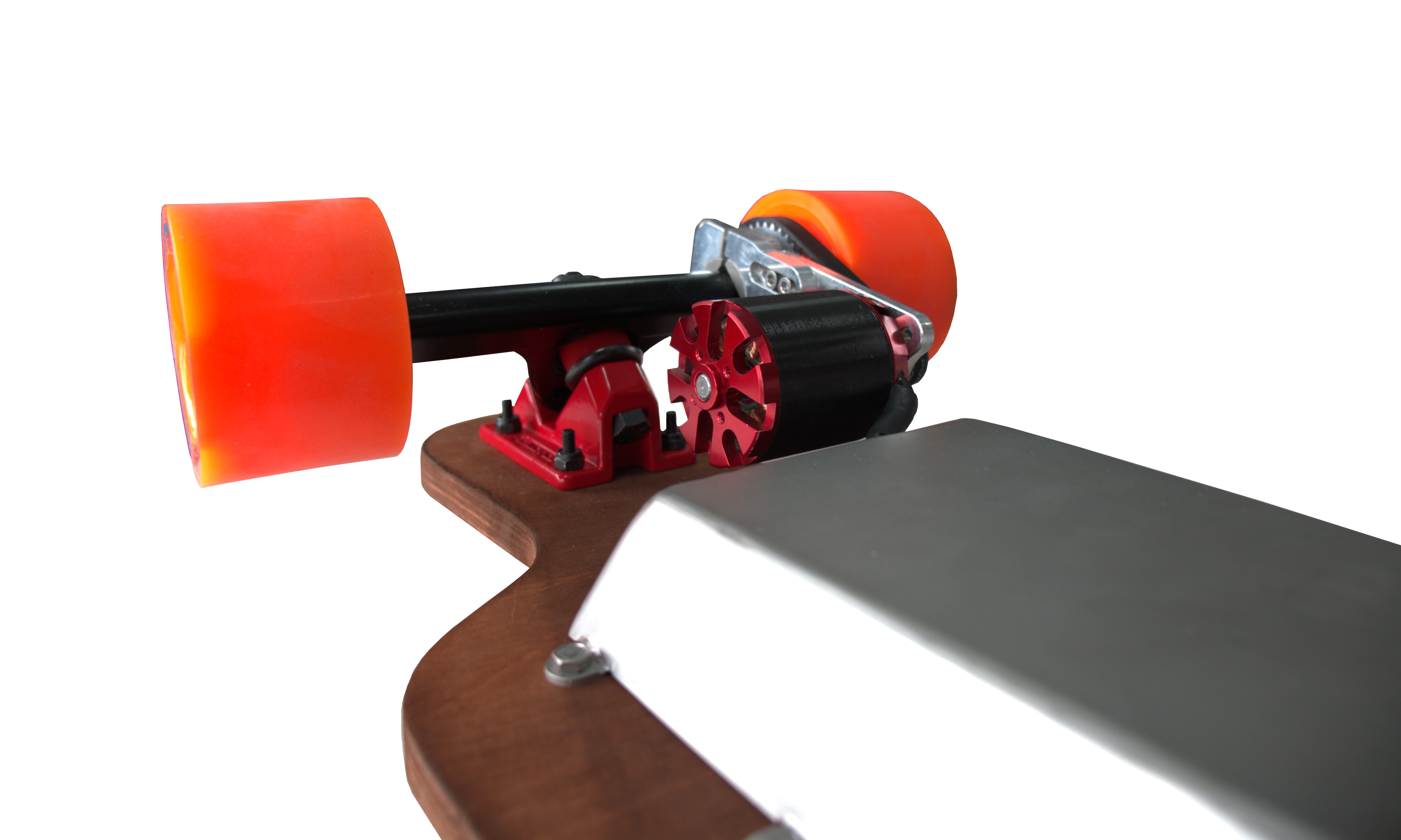
- Custom Motor Mount
THE CONCEPT
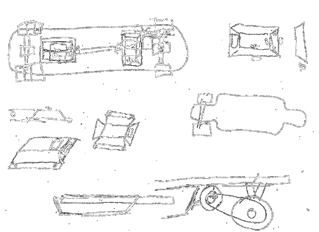
I started by drawing up a few concept sketches of how I wanted the board to look. I mainly focused on the electronics enclosre underneath as it's design dictated the volume I could work with when designing the electronics.
I knew I wanted two enclosures, one for the speed controller and the 433Mhz communication, and one just for batteries.
I would then connect the two enclosures togeather through a slot I in the longboard itself so that no wires were visible on the bottom of the board.
THE LONGBOARD
After some trial and error designing my own deck, I decided to look at what other people have done to get some inspiration.
I found a collection of templates simply titled Churchill, and decided to use the ST-29 model.
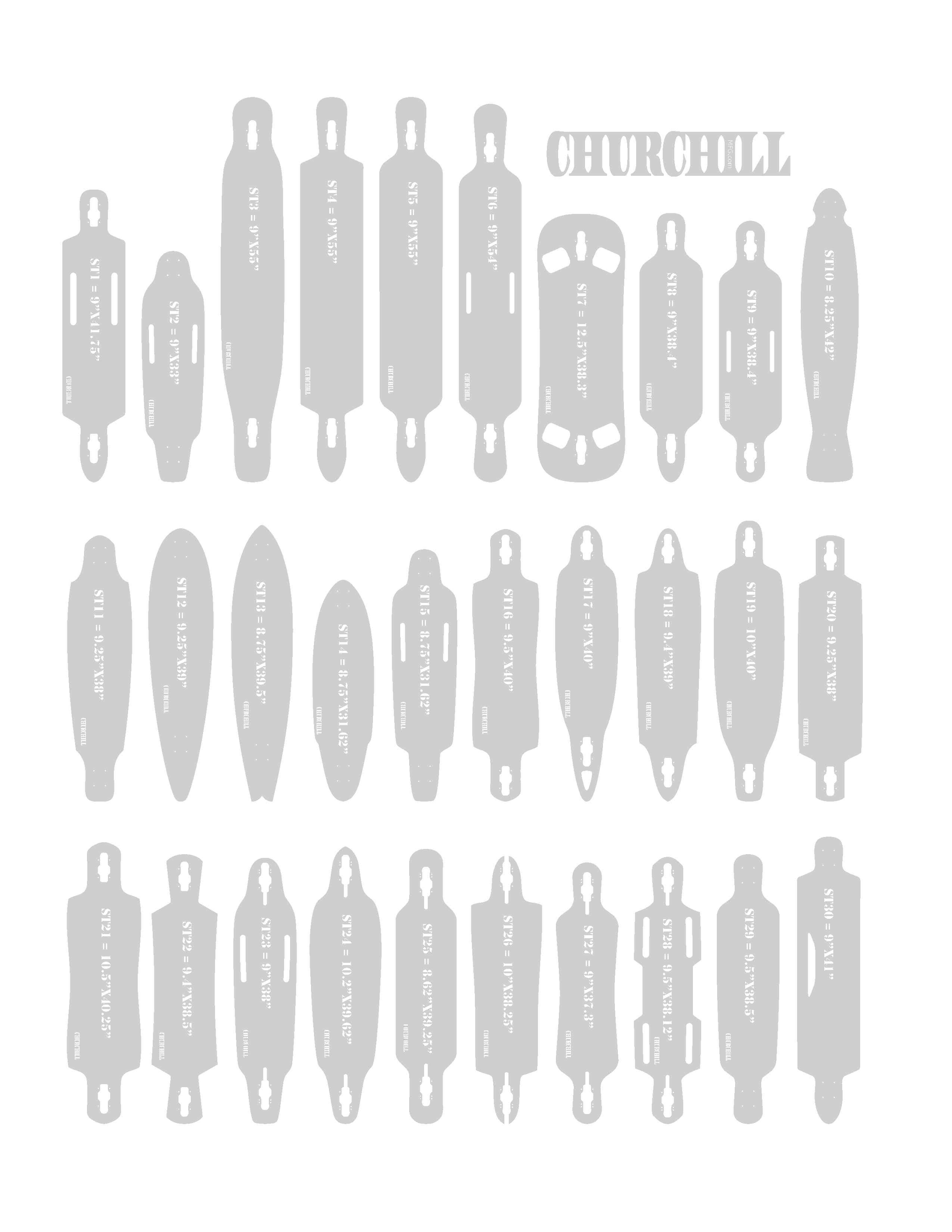
When I looked for these again for this article I couldn't find the templates, however I managed to dig all of them up. This took hours! as I could only find a few of the templates on my old hard drive, but luckily after a few hours on Archive.org I finally found them all.
I have decided to try to preserve these templates HERE in case you want to use them yourself.
Back to the point. I bought some 4mm (1/8 Inch) plywood and some wood glue. I then cut the plywood into three pieces and sketched the general outlines of my longboard as a guide.
I then milled a channel right down the middle of one of the plywood sheets. The purpose of this channel is to hide the main power cable from the battery enclosure to the speed controller enclosure.

Once I had cleaned up the milled channel, I drilled two holes through a second piece of plywood that matched up with the end of the milled piece. I then put a generous amount of glue onto the plywood sheets, and glued them together.
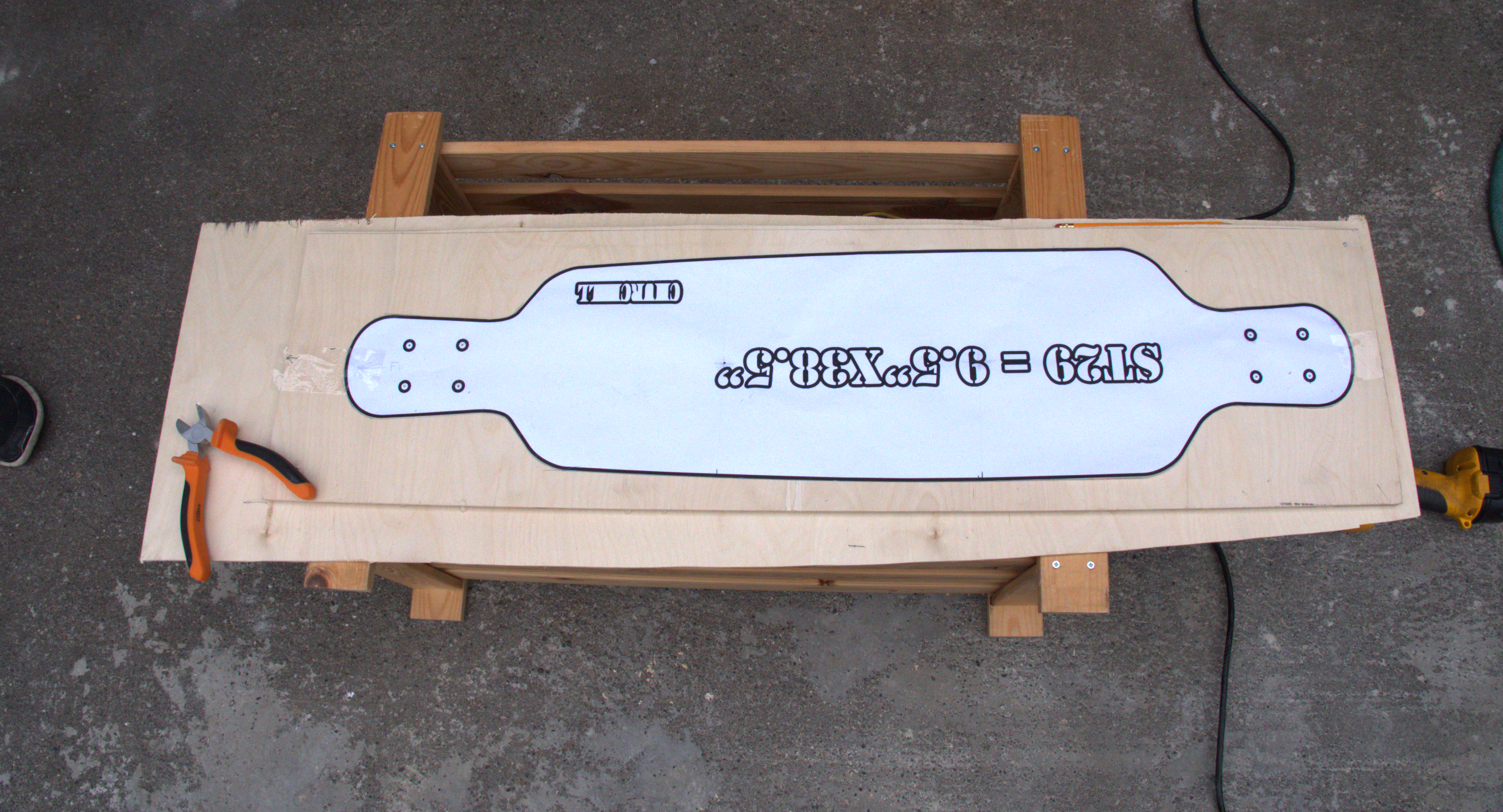
Once the glue had dried I used a plotter to print out the template I chose. I then glued the template to the longboard and cut it out using a jig saw.
THE ENCLOSURE
Once the longboard had been cut, I started working on the enclosure.
I made the CAD model in solidworks and used the sheetmetal function to make the fabrication step easier. Once I was happy with the enclosure, I had it laser cut out of 316 Stainless Steel.
It was then just the matter of lining the pieces up and TIG welding them. I put a few holes in the model in case I needed to route some cables later, however they were unused and covered with a blind cable gland.

THE ELECTRONICS
I started by researching how people have done electric skateboards in the past, and found that most people use a Brushless Direct Current (BLDC) motor for its rediculous power output and small size.
To make most BLDC motors spin you need three phase power, not mains power, but three offset phases of around a perticular voltage. My motor happend to be specified for up to 30V so I decided to run it on two 22.2V batteries in parallel.
Running the batteries in paralell doubles the longboard's range, and distributes the load more evenly on the batteries.
The batteries however, cannot directly drive the motor, and require an Electronic Speed Controller (ESC) to change the batteries DC output, to a signal that can drive the motor at variable speeds.
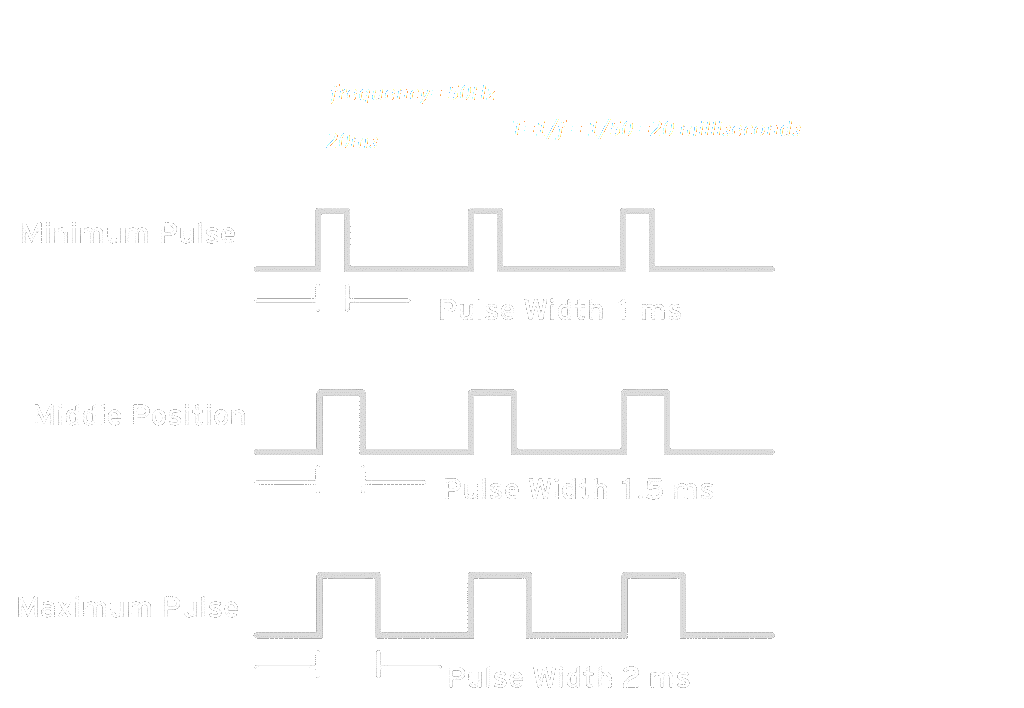
ESCs work simularly to those small hobby servos most of us are familiar with. It uses a specific PWM signal of 50Hz with a dutycycle from 1ms to 2ms. These dutycycles represent 100% speed clockwise and 100% speed counterclockwise respectively. The middle (1.5ms) represents no movement of the motor.
You can read more about BLDC motors and ESCs HERE
I decided to use an ATTiny85 to generate the PWM signal based on a potentiometer input.
While looking for a housing for my controller, I stumbled upon an unused Wii Nunchuck. I figured it would make a great controller, and luckily for me the potentiometer defaulted to the middle.
That meant that when I provided no input on the controller, the longboard would not move. I also decided to use one of the controller's buttons as a "Dead Man's Switch" which means that the ATTiny85 will create the PWM signal while that button is being held.
I made a small PCB to interface with the battery module as well as the ATTiny and the RF transmitter. Here you can see the circuit diagram for the controller.
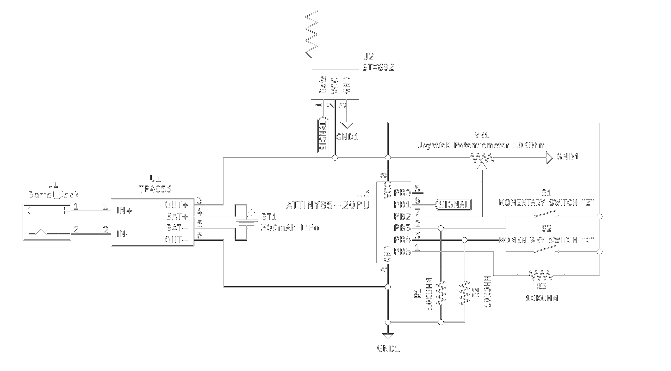
After I got the controller built I decided to work on the receiver. After I had connected everything on a breadboard to test the functionality, I realized that the SRX882 had some trouble interfacing with the Speed Controller.
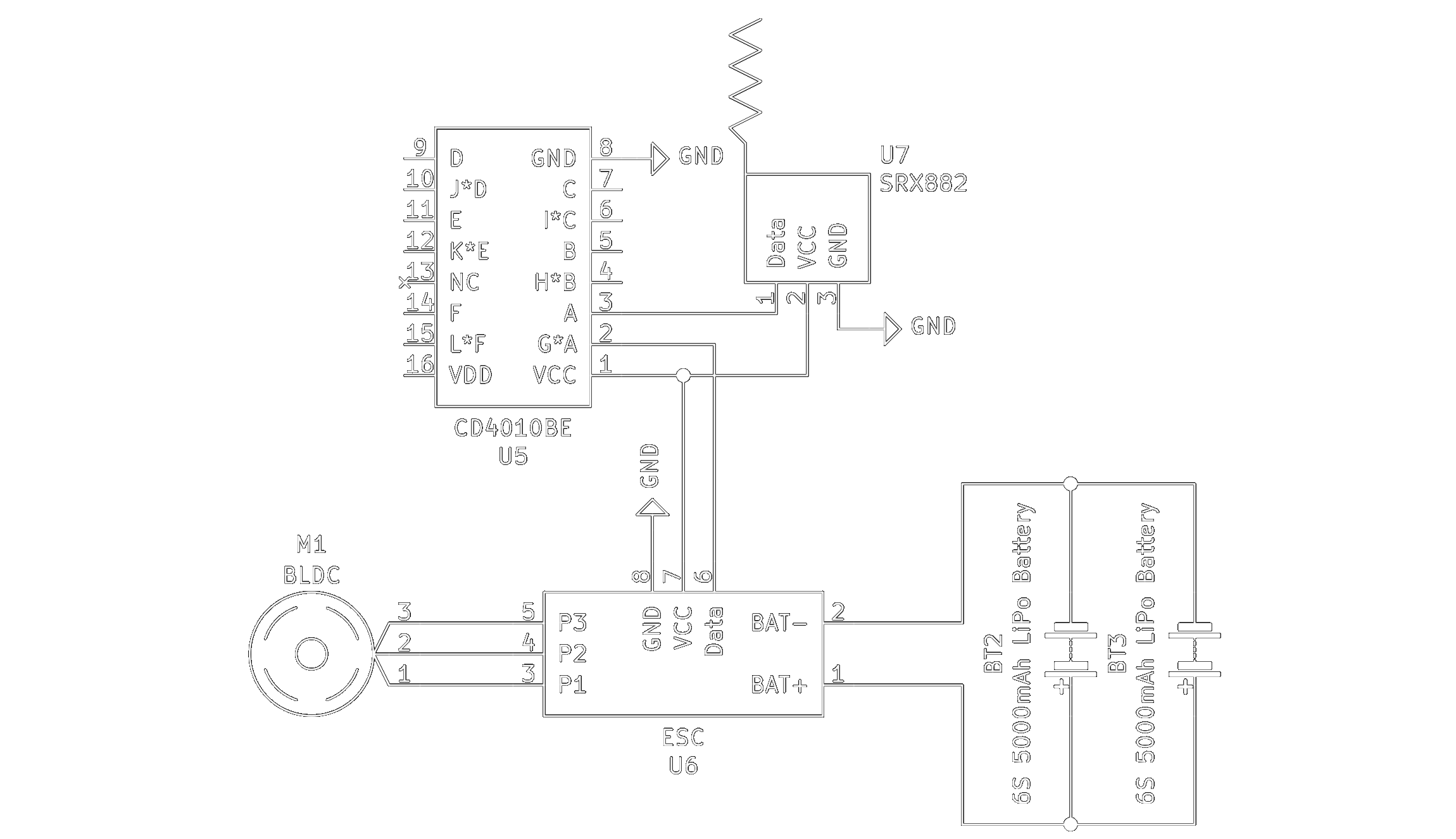
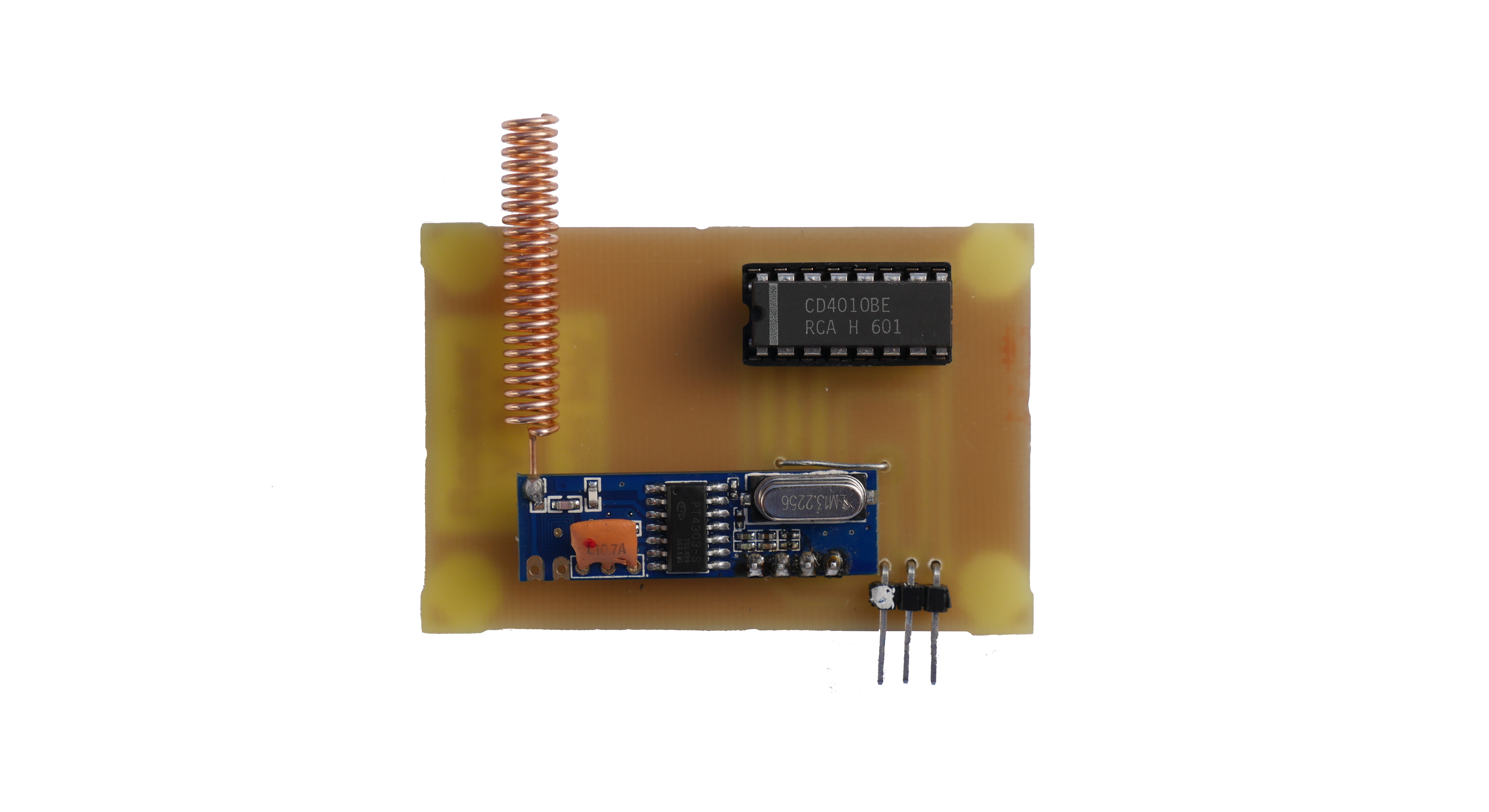
I fixed the problem by inserting a CMOS Hex Buffer inbetween the signal from the receiver and the ESC. After I had established functionallity, I designed the receiver PCB.
Luckily for me the ESC had a 5V output that I could use to power the receiver and the CMOS buffer, which made the circuit quite simple. Here is a circuit diagram that shows the complete circuit.
THE SOFTWARE
I wrote the software in C++ using the ArdunioIDE. I utilized the SoftwareServo.h library to generate the PWM signal, which worked out great.
Once I had made the program so that it would only output a signal while the dead man's switch was being held, I implemented a ramping function which I tuned to smoothly accelerate even if the joystick is pushed all the way up.
While I was at it I also decided to use the second button on the controller as a sort of cruise control. It works by holding the current speed while it and the dead man's switch are being pressed.
This part is was written from memory, as I have since lost the code. This code is simple enough to rewrite form the explaination above, so feel free to try it out.
THE ASSEMBLY
I attatched the ESC, and receiver in their electrical enclosure using m3 bolts and nuts. As the ESC can get quite hot, I applied some thermal paste between its heat spreader and the steel enclosure.
After I had mounted the electronics I soldered a pair of XT-60 Connectors on the ESC and battery cables. While XT-60 Connectors are only technically rated for 60A of continous power, and the ESC and motor are rated for 80A. They will rarely ever run that much, as the peak current is usually only reached when accelerating from a standstill.

Once I had those connectors soldered on I fed the motor wires through a rubber grommet and soldered them directly to the ESC.
I then proceeded to mount the enclosure to the longboard deck using short wood screws, which held it there tightly.
I made a slight modification to the Wii controller and added barrel jack connection to the bottom for charging, instead of the built in USB connector.
Getting the controller back together was a bit of a hassle, but in the end, everything fit quite well.
The one thing I wish I could have made myself but couldn't was the motor mount. Unfortunately 3D printing it just wouldn't hold up to the torque created by the motor.
The mill I planned to use to mill the pieces out of was broken and waiting to be serviced, so I ordered the mounting brackets online from Alien Power Systems.
I had never really heard of them before so I was skeptical at first, but once I received the mount, I was blown away by it's quality.
THE CONCLUSION
This project was quite simple, yet it took a long time to do. This was my first time using 433Mhz RF communication, and the first time I worked with high current devices.
The design went smoothly, and didn't take long at all. However building the longboard took way longer than I had anticipated. This was partially due to the fact that I had to remake the skateboard deck, as the first glue that I used expanded a little while it cured which shifted the hole allignment.
The range on this longboard is rediculous. I haven't actually measured it but if I do a straight comparison between the battery size on my Boosted Board and this, it should reach well over 25km or over 15 miles.
I have not tested it's top speed, as the deck is a bit stiff which causes some wobbles at high speed. But I will update this build log if I get around to it.
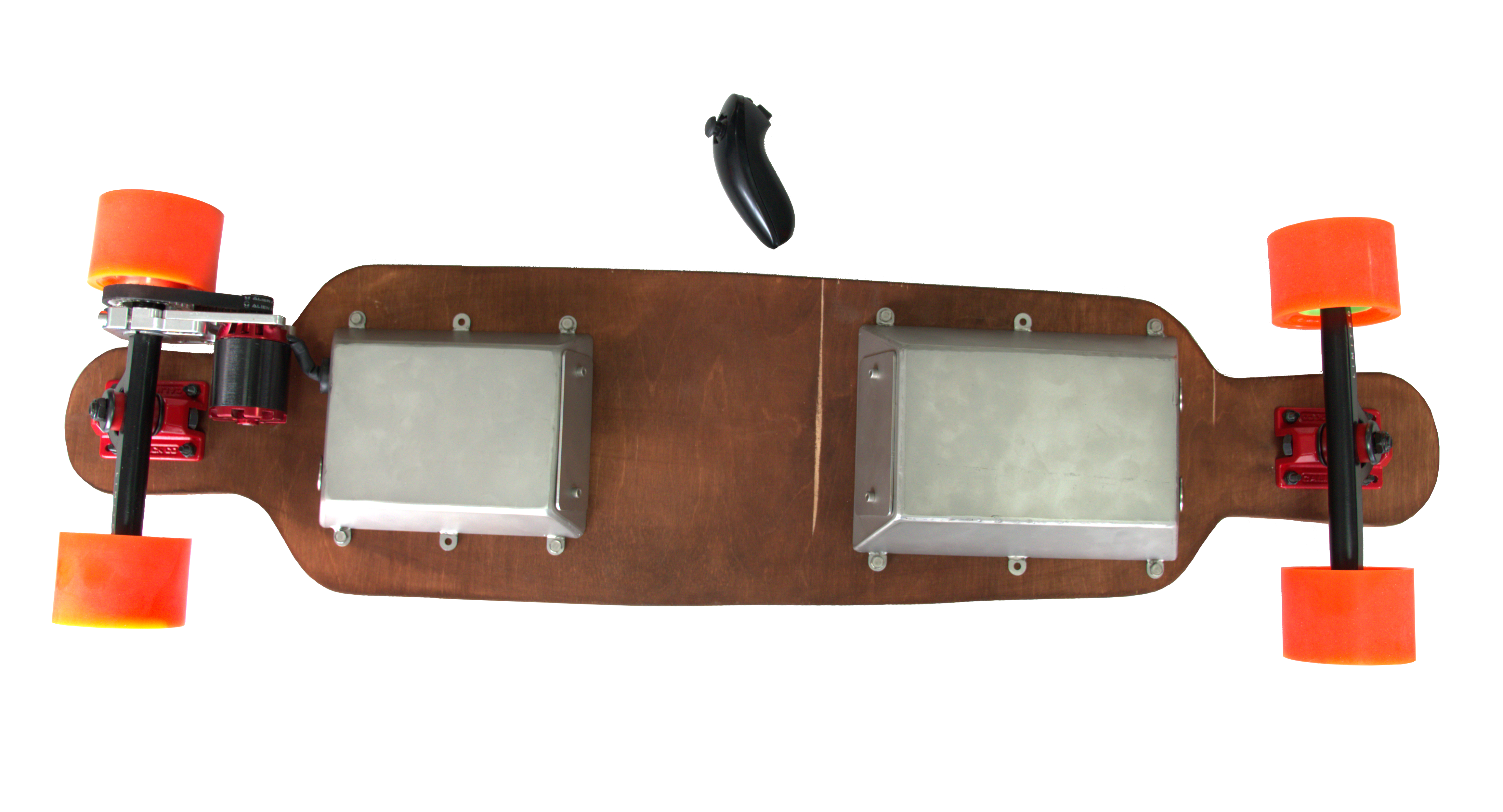
Thank you for reading, here are some pictures of the finished product.
--
SINDRI THOR