--
This is an overview of how my team and I designed and built a basic robot arm. This project was our final project for the class Mechatronics I. I took the class as part of my studies at Reykjavik University in fall 2021.
SPECIFICATIONS
- 500g Lift Capability
- Full Three Dimensional Motion
- Inverse Kinematics
- Web Socket for Control
BILL OF MATERIALS
- 60Kg Bi-Axial Servo
- 12V 40A Power Supply
- 2x 20A Buck Converter
- Custom PCB
- Raspberry Pi 4B 4Gb
CONCEPT
We started working on this project a week after we started this course.
We started by looking online, to see how robotic arms are traditionally made. We settled on what we called the "Servo Joint" type, which has biaxial servo motors as its joints. This means that we can keep the weight down, as we don't need any more material around the joint.
Here is a simple sketch we made showing how we wanted the geometry to work.
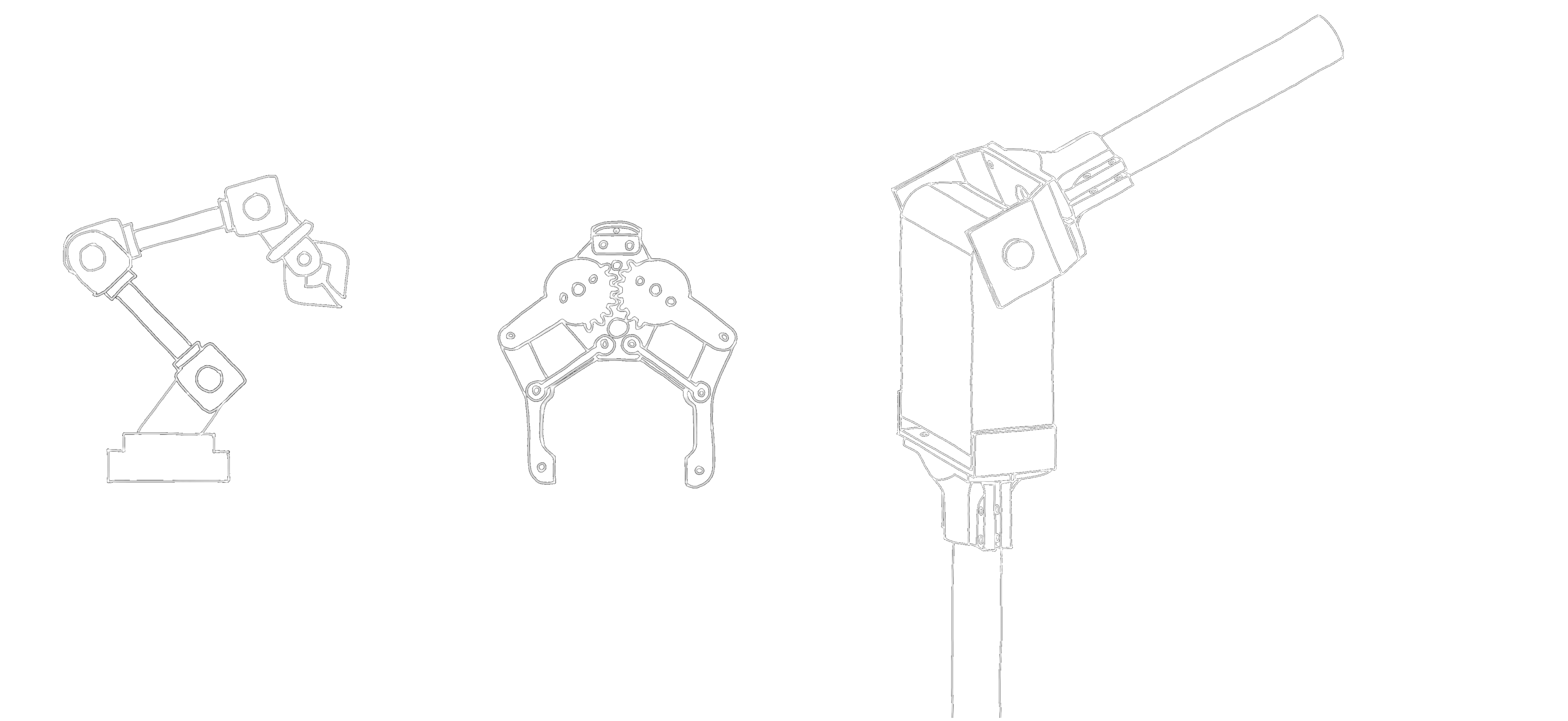
We knew from the start that we wanted to do 5 Degrees of Freedom. One would be for rotation, then three tilting arms, and then another rotating arm on the gripper.
That means we would need three high powered servos, one medium powered, and one standard hobby servo.
We figured that the rotation and tilt of the arms needed bigger motors than the tilting and grabbing mechanism of the gripper, so thats what we ordered.
Our goal was to be able to lift around 500g, so the design had to account for that.
THE DESIGN
To be able to offset the weight of the arm itself and lift 500g, we decided to use a 60kg servo motor. If we make some assumptions about the weight of the arm, we could have the arm reach up to 250mm (10 Inches).
This proved to be correct as there was also some unforseen stiction in the servos, which offset the weight of the arm quite significantly.
We knew we had some 16mm carbon fiber rods layign around, so we decided to use them as the main arms of the robot. This reduced the weight quite significantly as well, which gave us a higher safety factor on our weight goal.
After some playing around we decided that a websocket would be the best way to control it, as it is easily modified to suit our needs and demonstrates an understanding of basic web development.
To do this we planned to use a Raspberry Pi Zero and a Teensy 4.0 as an ADC. We later found out that wouldn't work so we switched the Pi Zero to a Pi 4B.
THE ELECTRONICS
As previously stated, we used a Raspberry Pi 4B 4GB as our main controller. The Raspberry Pi was paired with an Teensy 4.0 which simply worked as a 6 channel ADC to allow for current monitoring on each motor.

The Teensy 4.0 was also used to control the servos as the Teensy's real time processing proved superior to the Raspberry Pi's during testing. and the Raspberry Pi's purpose was to control the websocket to handle the inverse kinematics required accurate movement in a Cartesian coordinate system.

The Teensy and the Raspberry Pi communicated using serial (RS-485), as it was the simplest communication to implement.
One of the more difficult parts of this project was to choose the correct motors. We had originally wanted to use BLDC motors, however that would have required absolute encoders for each motor, which would have increased the complexity of the project.
After having looked at multiple servo motors, we settled on the RDS5160, a 270° bi-axial servo motor with 0.7Nm of torque when driven at 8.4V. We found a seller which included mounting hardware and bearings with the motors, which seemed to fit our needs perfectly.

A feature of servo motors is their ability to know their position, even after being powered off, which eliminated the need for encoders, and a homing mechanism. These would be used to move the arm itself, however smaller and cheaper MG995 motors were used for the gripper.
To measure the motor current the ACS724LLCTR-10AB-T Hall-Effect current sensor was used. It supports up to 10A of current, and outputs 200mV per amper of current that goes through it.
This setup was ideal as we already had the Teensy to control the motors, and simply utilized the spare ADC pins to detect the voltage.
One down side of the hall effect sensor was that it was bi-directional. Meaning that with a supply voltage of 5V, it's output was 2.5V with no current flowing. This would not be ideal as any more than 4A of current would exceed the maximum input voltage of the Teensy's ADC.
A small Op-Amp circuit was made to lower the voltage by 2.50V and amplify the signal with a gain of 1.6. This configuration lets the Teensy detect the current with a little more accuracy, as it now recieved 320mV per amper, resulting in a measurement range of 0V-3.2V
The decison was made to use A 12V 40A power supply, as we had one on hand from another project, and to use two commercial buck converter modules to step down the voltage for the 8.4 and the 5V. The 5V for the Raspberry Pi and Teensy would be supplied by an RPM5.0-2.0 buck converter which would be fed with 8.4V
This was done to reduce the chance of overcurrent events dropping the voltage to the Raspberry Pi which could damage it.
A schematic was drawn, showing how each component interacted with the other. A PDF of the Schematic can be found HERE.
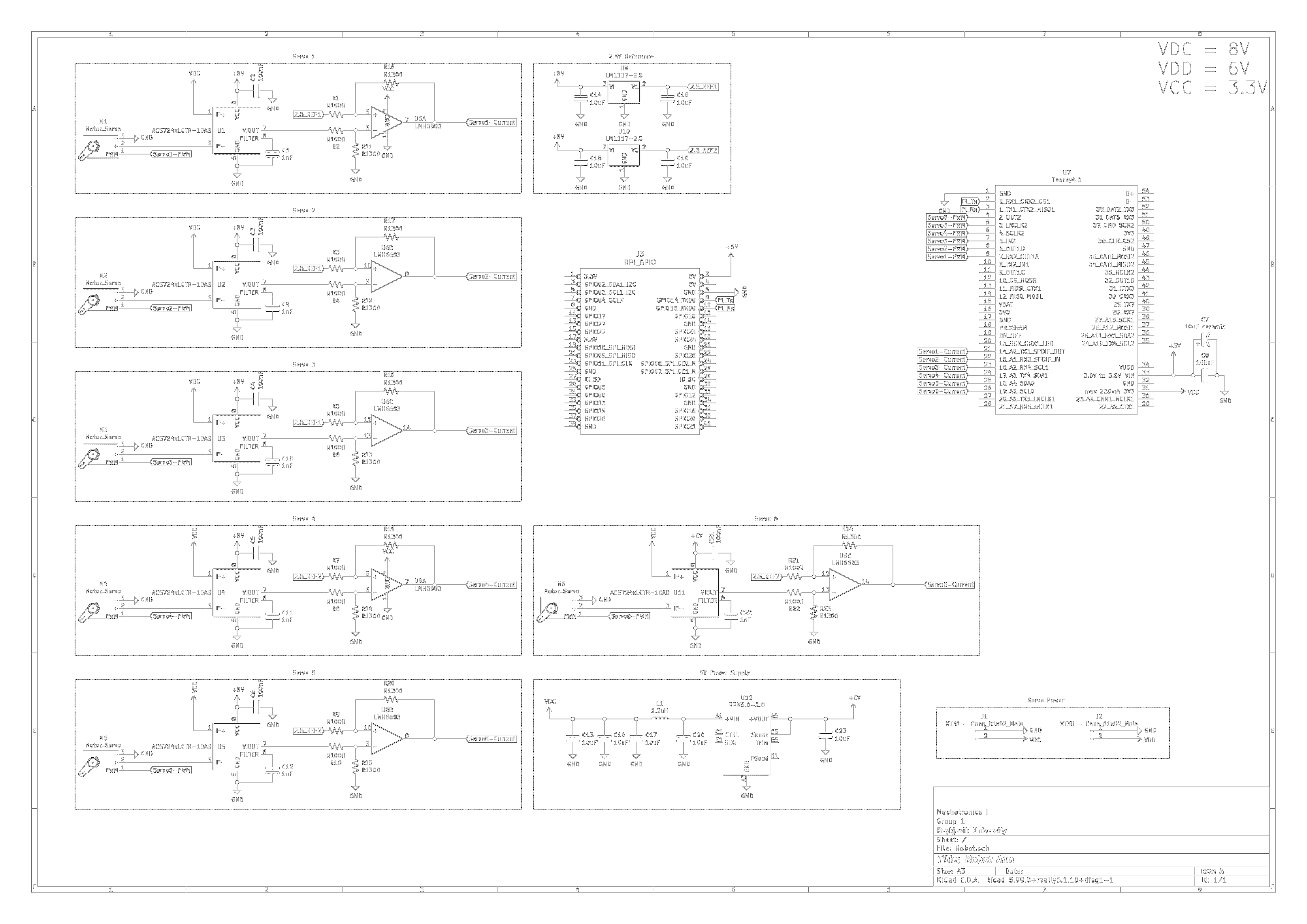
A custom PCB was then made to house all the components. Special consideration for tracewidth had to be taken into account when designing the PCB as the motors chosen for this project have a theoretical maximum current of 6.5A when driven at 8.4V.
Using the IPC-2221 standard for PCB trace width, a trace width of 4.2mm was deemed enough for the 3 RDS5160 motors, and the same was given to the MG995s. By having the PCB be 2oz/ft^2 thick, we could expect a temperature rise of 30°C on the traces, if all motors are stalled.
A general layout of the PCB as well as a bill of materials can be seen here: Robot Arm PCB BOM .
SOFTWARE
( WIP )The websocket allowed the user to control the movement of the robot as well as the gripper. Since we were already monitoring motor current, we implemented a system of automatically detecting item pickup by the gripper.
--
SINDRI THOR