--
This project focuses on designing and creating an Advanced Power Distribution Module (PDM) for RU-RACING’s RU20 Formula Student race car. This project was completed as an independent project for the T-629-INDE course at Reykjavik University by Sindri Þór Harðarson, under the supervision of Guðmundur Kristjánsson.
Introduction
A Power Distribution Module (PDM) is responsible for distributing electric power to various components or circuits and protecting them from overcurrent and shorts due to equipment failure, typically using in-line fuses. The PDM designed for RU-RACING's Formula Student race car incorporates built-in troubleshooting and data logging capabilities. These features are facilitated through sensors that communicate with the car’s CAN (Controller Area Network) and LoRa (Long Range Radio) networks, enabling remote monitoring.
The team decided to use nine channels to manage different components, allowing for future expansion of the car's features. The design adheres to the Formula Student Germany rule book, ensuring competition compliance.
Design Process
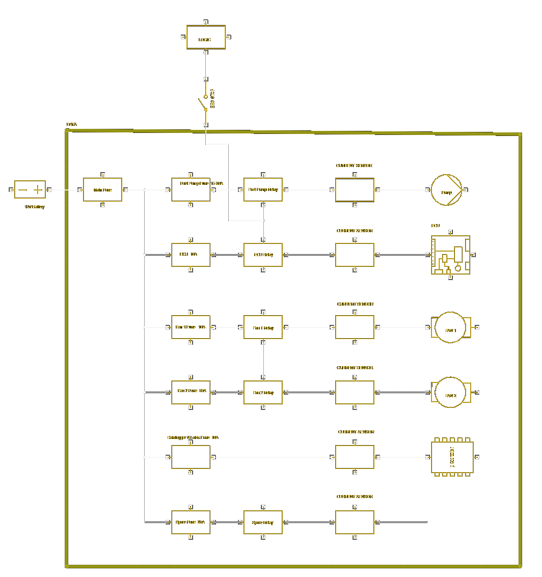
The design process started with a simple block diagram, depicting six out of the nine channels for simplicity. This initial design provided a clear understanding of the challenges to be addressed.
Originally, the design involved splitting the system into two separate PCBs, but this proved difficult as transferring power between layers required expensive high-power connectors. The concept was that in case of a failure in any of the relays or logic components, a direct bridge could be connected in parallel with the logic, allowing the equipment to function even without the logic circuit. However, it was ultimately more practical and safer to have a single PCB handle both the logic and power distribution, as the car should never be run without the logic circuit due to safety regulations.
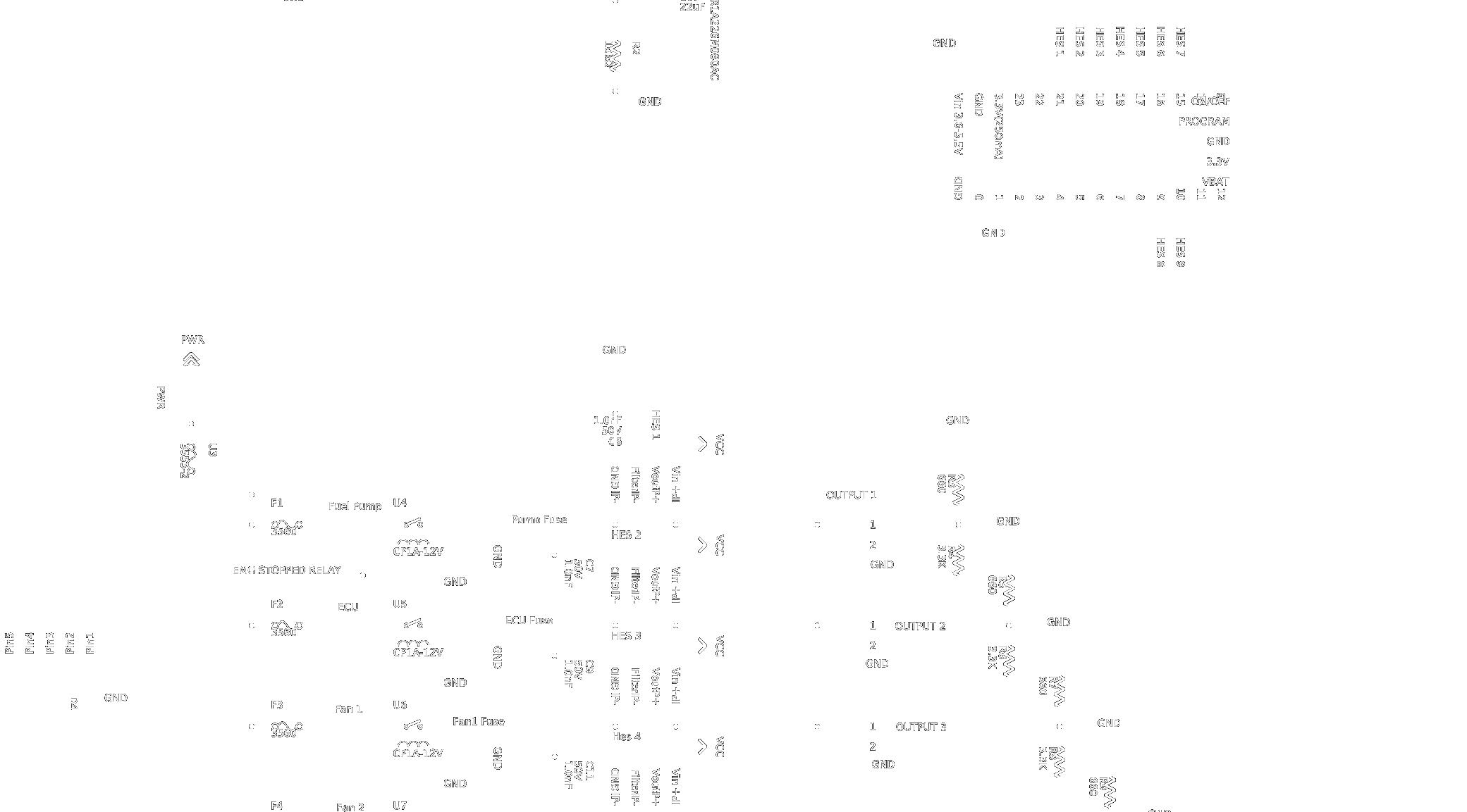
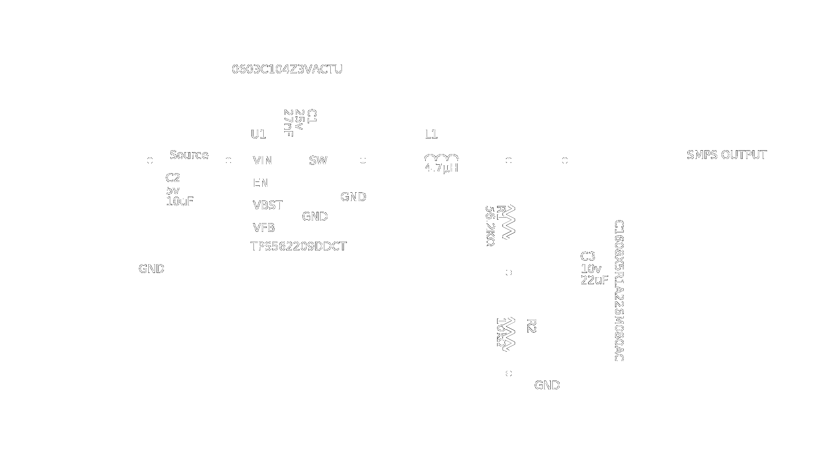
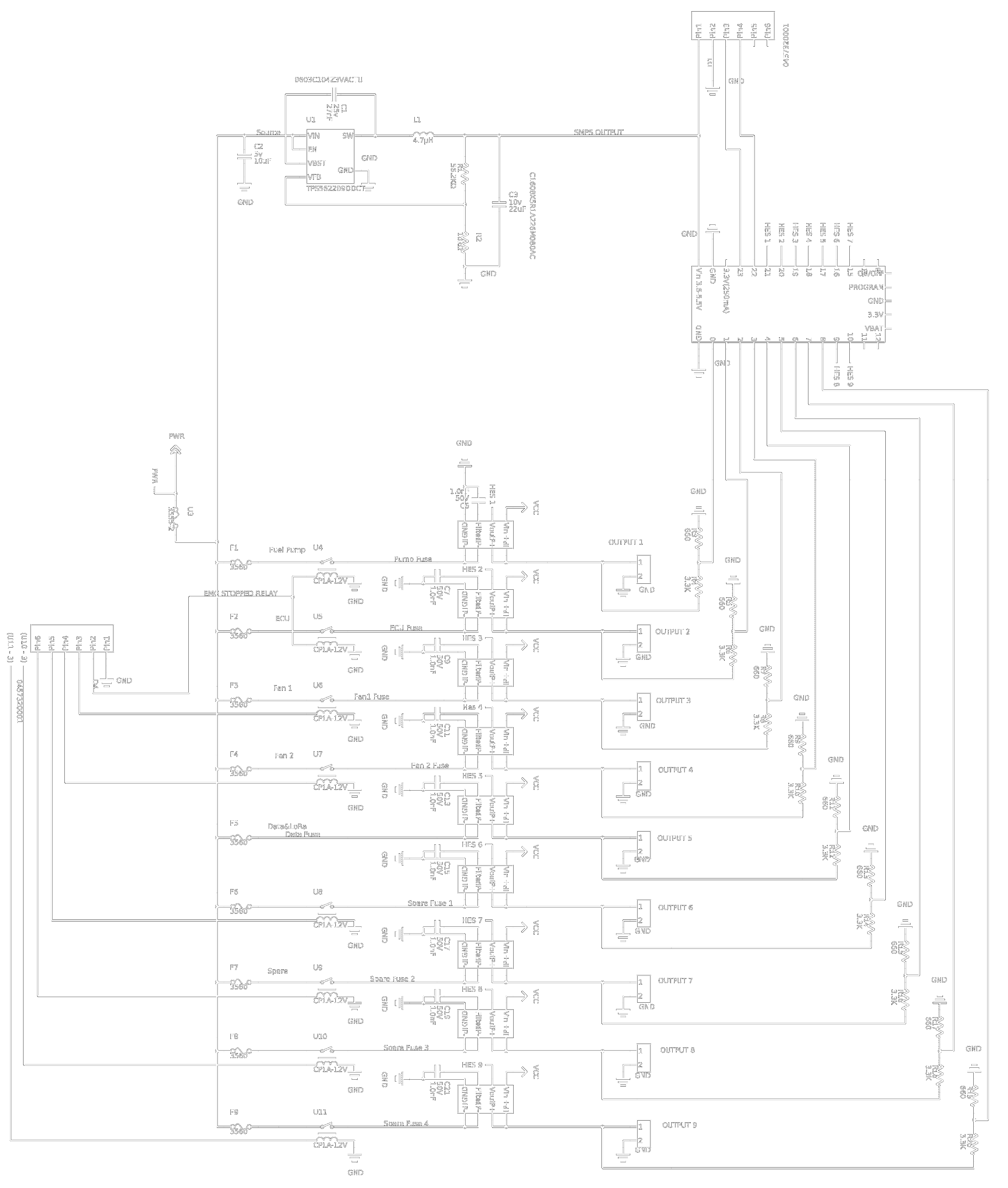
After finalizing the block diagram, work began on the schematic, which was divided into three sections: Power, SMPS (Switch Mode Power Supply), and Logic CAN. The power section was designed to be expandable, with each block being almost identical to the next, simplifying layout and future modifications.
The first component in the power section is the fuse holder, which can house any ATC fuse depending on the use case. Next is the relay, controlled by an external signal received via an 8-pin Molex 0457320001 connector. The current sensor follows, connected in series with the current channel and leading to an XT30 power connector. The V-Out signal from the current sensor goes directly to a pin on the Teensy. Finally, a pair of voltage dividers are connected in parallel to check if there is voltage on the channel.
Independent voltage measurements, though seemingly redundant, serve as a diagnostic tool. If there is no current flow but voltage is present, it can be assumed that the component has failed. Conversely, if voltage is not measured, it can be assumed that the fuse is blown. This diagnostic capability provides critical information to the pit crew, eliminating electrical troubleshooting and reducing repair time.
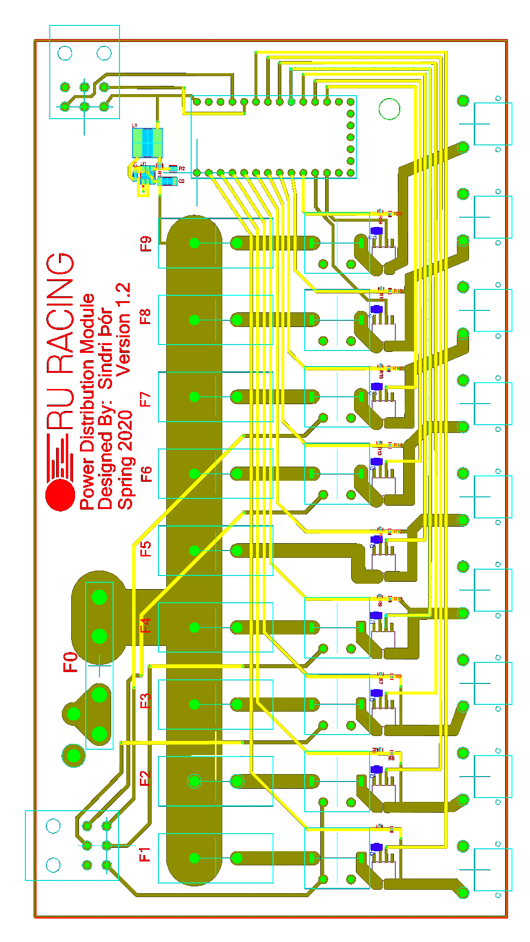
Printed Circuit Board
One of the biggest challenges in designing a PDM is ensuring components can handle the high current running through the device. The first and arguably most important component to tackle is the PCB itself. After researching, a manufacturer that specializes in high-current PCBs at an affordable price was selected. The PCB was made from FR4-HIGH TG 180C, a self-extinguishing woven fiberglass cloth with an epoxy resin binder, with a copper thickness of 6oz/ft² (0.2082mm).
With the copper thickness determined, the minimum trace width could be calculated. The highest current drawn by a single channel was around 8.5-9A, so a 10A capacity was used for the width calculation to provide some headroom for potential issues. The following equations were used to determine the trace widths:
Area = c * sqrt(I) / (k * (ΔT)^b)
Where I represents Current (A), ΔT is the allowed temperature increase on the PCB (°C), and k, b, and c are coefficients from the IPC-2221 Standard on Printed Board Design (k = 0.024, b = 0.44, c = 0.725 for external layers).
Width = Area / DCu
Where DCu is the copper thickness in millimeters.
The acceptable temperature change (ΔT) was set at around 10°C, requiring the traces to be 3.12mm thick for 10A at a copper thickness of 0.2082mm. Signal traces that do not carry much current were designed with 0.6mm widths, capable of handling up to 4.11A.
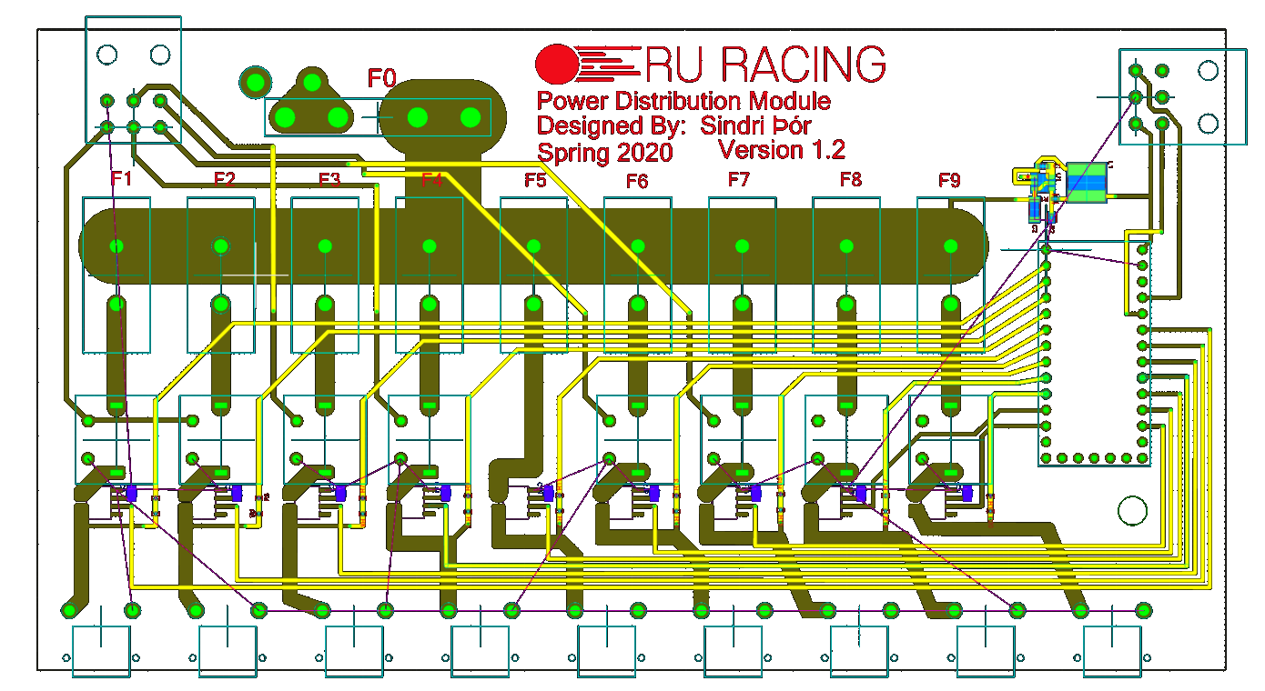
The PCB layout was carefully planned to ensure efficient power distribution and signal integrity. The main input, which could draw up to 50A, required special consideration for trace width and placement. Ensuring that all components were up to spec with the high current requirements was crucial for the reliability and safety of the PDM.
Components
The components were chosen based on several criteria, including size, weight, maximum current, and price. In Formula Student, it's essential to use properly specified components that can handle a full system failure in case of a crash. The critical components included fuse holders, relays, power connectors, and a PIC for CAN communications.
The main fuse holder, Keystone 3555-2, was selected for its size, weight, and price, with a maximum current rating of 50A, which should not be exceeded. For each of the nine channels, Keystone 3560 fuse holders were chosen for their excellent price-to-performance ratio and interlocking capability, which enhances rigidity and longevity.
The relays chosen were Panasonic CP1A-12V Automotive Relays. Their compact size and automotive specifications made them an excellent choice for reliability and performance in the PDM.
For CAN communications, the Teensy 4.0 development board was used. It features three CAN connectors, 23 dedicated I/O pins, and an ARM Cortex-M7 processor running at 600 MHz. The Teensy supports C++ programming via the Arduino IDE, simplifying the programming process.
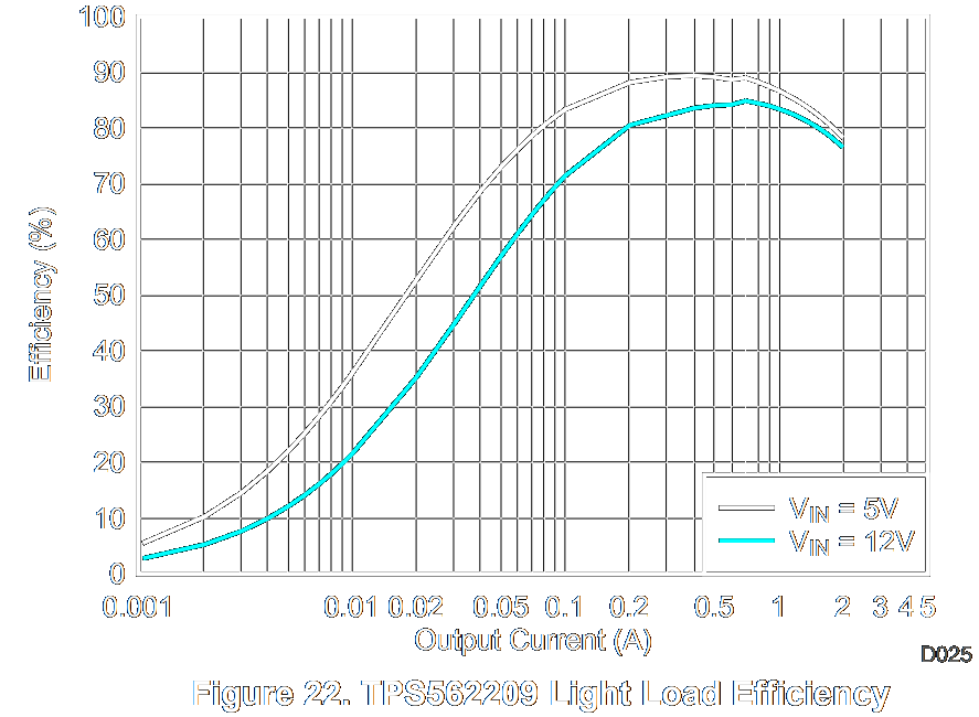
The Teensy is powered by a Switch Mode Power Supply (SMPS), which converts the car's 12-14V LiFe-Po battery voltage to 5V. The SMPS is built around the Texas Instruments TPS562209 Synchronous Step-Down Voltage Regulator, following the recommended schematic. This IC can deliver up to 3A of current at any voltage from 3-17V, sufficient for the Teensy and its I/O requirements. At an estimated 400mA load, the efficiency is over 82%.
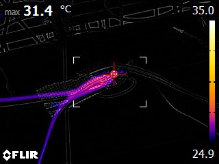
The current sensor, ACHS-7124/7125 Hall Effect-Based Linear Current Sensor IC, met strict specifications regarding current tolerance and size. It can sense currents from -50A to 50A with a sensitivity of 50 mV/A, providing the Teensy with 2.7-3.3V depending on the channel's current draw. Initial skepticism about the IC's performance was addressed through testing, where it handled 15A for over an hour without exceeding 31.5°C, which was about 8.5°C above room temperature.
The power connectors for the PDM's nine outputs are XT-30 connectors, known for their corrosion and spark-resistant plugs that ensure a solid high-amp connection, allowing up to 30A of constant current.
Schematics and Layout
Conclusion
Designing the PDM required balancing compliance with regulations, reliability, and cost. Despite challenges, the design aims to offer an advantage over current market options. Testing is limited due to the COVID-19 pandemic, but the designer is hopeful for its success given the extensive research and effort invested. The PDM will be manufactured and assembled once PCB factories reopen, and deployed in the RU20 Formula Student race car.
Bill Of Materials
| Reference Designator | Description | Manufacturer | Qty | Part Number |
|---|---|---|---|---|
| C1 | SMD Ceramic Capacitor 27nF | Vitramon | 1 | Capacitor 27nF |
| C4-C12 | SMD Ceramic Capacitor 1nF | Vitramon | 9 | VJ0603Y102KXACW1BC |
| C2 | SMD Ceramic Capacitor 10µF | Vitramon | 1 | Capacitor 10uF |
| C3 | SMD Ceramic Capacitor 22µF | Vitramon | 1 | Capacitor 22uF |
| D2 D3 D5-D11 | AMASS XT30PW XT30 PCB Connector | AMASS | 9 | XT30PW |
| D4 D1 | Connector Header, Right Angle | Molex | 2 | 0469990016 |
| F1-F9 | FUSE HOLDER BLADE 20A PCB | Keystone | 9 | 3560 |
| L1 | Semi-shielded Power Inductors | Bourns | 1 | SRN6045-4R7Y |
| Q1-Q9 | Current Sensor 40A Hall Effect | Broadcom Ltd | 9 | ACHS-7124-000E |
| R1 | AC0402 56.2KΩ 0.0625W 1.00% | Yageo | 1 | AC0402FR-0756K2L |
| R2 | RES Thick Film SMD 10kΩ 1% | Vishay | 1 | CRCW040210K0FKED |
| R4 R6 R8 R10 R12 R14 R16 R18 R20 | Generic Resistor (3300) | Generic | 9 | Resistor (3300) |
| R3 R5 R7 R9 R11 R13 R15 R17 R19 | Generic Resistor (660) | Generic | 9 | Resistor (660) |
| U1 | 3A Step-Down Voltage Reg. | Texas Instruments | 1 | TPS562209DDCT |
| U2 | Teensy 4.0 Development Board | PJRC | 1 | Teensy 4.0 |
| U3 | Blade Fuse Block 50A 500V | Keystone | 1 | 3555-2 |
| U4-U11 | RELAY AUTOMOTIVE SPST 20A 12V | Panasonic | 8 | CP1A-12V |
References
- IPC-2221 Generic Standard on Printed Board Design. [Internet]; [cited 2020 Mar 10]. Available from: IPC-2221.pdf
- Formula Student Germany 2020 Rulebook. [Internet]; [cited 2020 Mar 10]. Available from: FS-Rules 2020 V1.0.pdf
- Fuse holder Datasheets. [Internet]; [cited 2020 Apr 12]. Available from: M65p40.pdf
- Panasonic CP1A-12V Relay Datasheet. [Internet]; [cited 2020 Apr 12]. Available from: Panasonic CP1A-12V Datasheet.pdf
- ACHS-7124/7125 Current Sensor Datasheet. [Internet]; [cited 2020 Apr 28]. Available from: https://docs.broadcom.com/doc/ACHS-7124-7125-DS
- XT30PW Male/Female Datasheet. [Internet]; [cited 2020 Mar 29]. Available from: XT30PW-F.pdf
- Molex Signal Connector 0469990016 Datasheet. [Internet]; [cited 2020 Mar 29]. Available from: PS-5556-001.pdf
- Teensy 4.0 Development Board Datasheet. [Internet]; [cited 2020 Apr 19]. Available from: https://www.pjrc.com/store/Teensy40.html
- TI TPS56x209 Switch Mode Power Supply Datasheet. [Internet]; [cited 2020 Apr 19]. Available from: tps562209.pdf
--
Sindri Thor