--
This project demonstrates how to use a buck converter with a USB-C power delivery breakout board to replace traditional batteries with a USB-C connector for continuous power. This setup is particularly useful for providing a stable power supply to devices that typically rely on batteries such as cameras, lights, etc. This setup could also be used with a USB-C battery bank to allow for much larger battery capacities than the original battery could offer.
Specifications
- Maximum Current: 3A
- Maximum Voltage: Up to 20V (depending on power supply)
Introduction
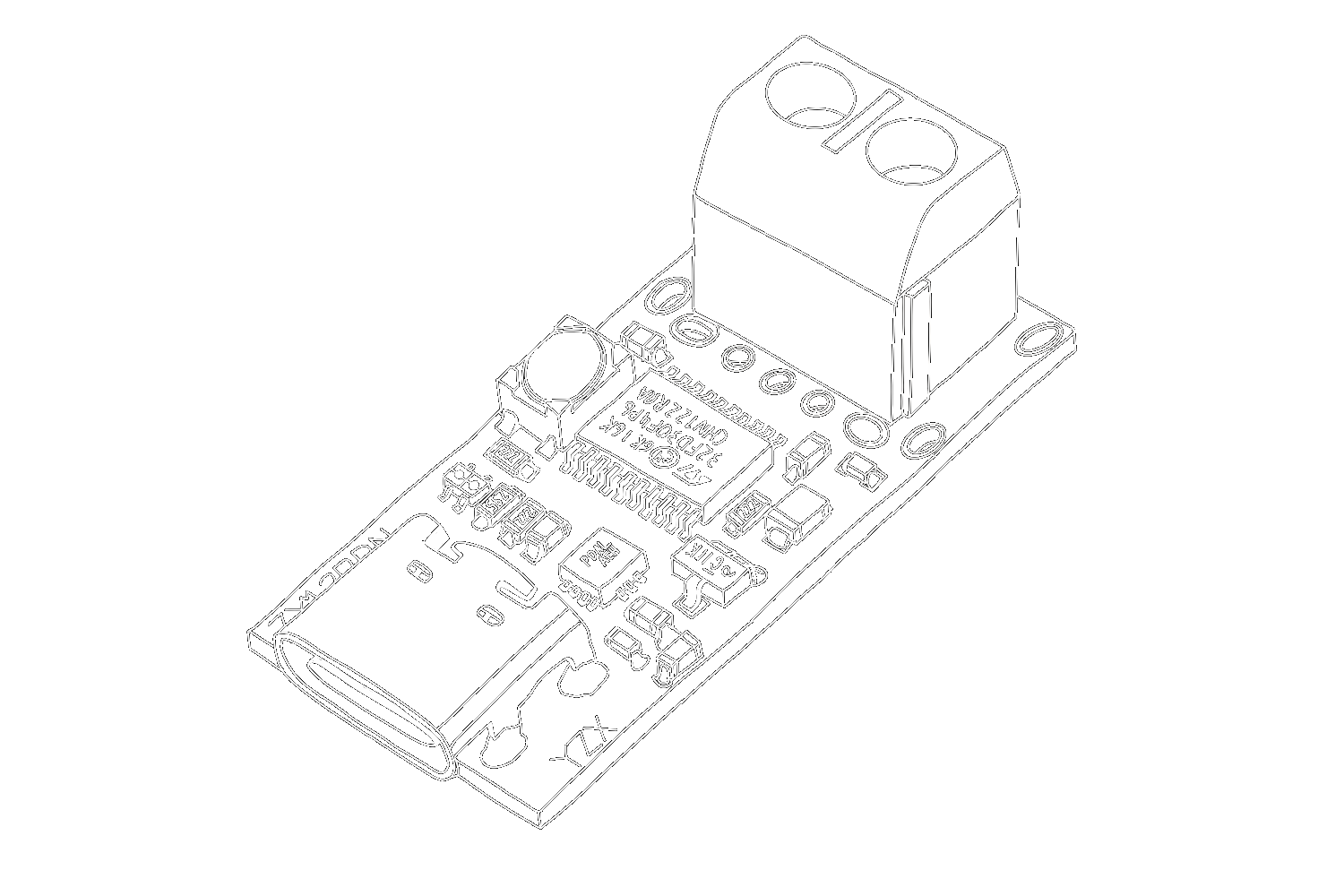
Using a buck converter with a USB-C power delivery breakout board allows for the replacement of batteries with a USB-C connector, providing continuous power. With the USB-C module, you can trigger different USB-PD protocols. The output voltage can be adjusted in 5 steps (5V, 9V, 12V, 15V, and 20V) via the button integrated on the module. The currently selected voltage can be read from the colour of the RGB LED integrated on the module.
If you happen to need any of those voltages, you're in luck! As you don't need the buck converter. If you need other voltages, select the closest voltage you can that is still above the required voltage, then use the buck converter to step down the voltage to your desired level.
The buck converter can deliver up to 3A of current, which is sufficient for most applications. This setup ensures that devices requiring stable power can operate continuously without the need for battery replacements.
NOTE: You can not get a higher voltage than your power supply is capable of, make sure you have a good USB-C PD wall outlet to take full advantage of this setup!
Setup and Connection
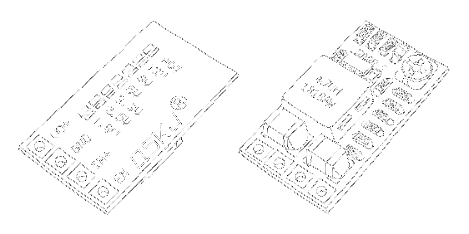
The buck converter is connected to the output of the USB-C power delivery breakout board. The enable pin is connected to the input pin through a 1KΩ resistor. The exact resistance value is not critical, and a slightly higher or lower value can be used without issue. The output of the buck converter is then connected to the device that requires power.
Camera Battery Example
In this demonstration, the setup is used to replace the camera battery on an aging Panasonic GH4. The voltage is set to 8.4V, which is the same as the battery at full charge. The outputs were then connected to their respective terminals on the battery.
However, the battery and camera have two extra terminals used to communicate the battery temperature and a data line. The camera will not turn on without the temperature terminal being correctly interfaced. Connecting a standard resistor between this terminal and the ground will trick the camera into accepting the battery. Ideally, a thermistor would be used to take advantage of the camera's over-temperature protection, but a resistor works sufficiently for this application. The resistance was determined by measuring the resistance between the T terminal and the negative terminal on the battery before disassembly and then using a resistor with the same value. In my case, that was around 10KΩ.

To acheive this the battery first needed to be disassembled. This can be quite dangerous so care needs to be taken not to puncture the cells inside. Once the battery has been stripped of its original components a small cut needed to be made in the bottom of the battery to allow the USB-C port to peek through the case. Finally the circuit was soldered as shown in Figure 3, crammed into the battery case, and closed with glue around the seam where it was opened.
Figure 3 shows a romantizised overview of the internals. Unfortunately the battery was so small that the two PCBS had to be stacked, with a piece of electrical tape isolating them from each other.
Replacing AA Batteries Example
Another application of this setup is to replace AA batteries in devices that require a stable power source. By adjusting the voltage to 3V, the buck converter can provide a stable power source for devices that typically rely on AA batteries. This setup is particularly useful for devices that are in frequent use and therefore require frequent battery replacements.
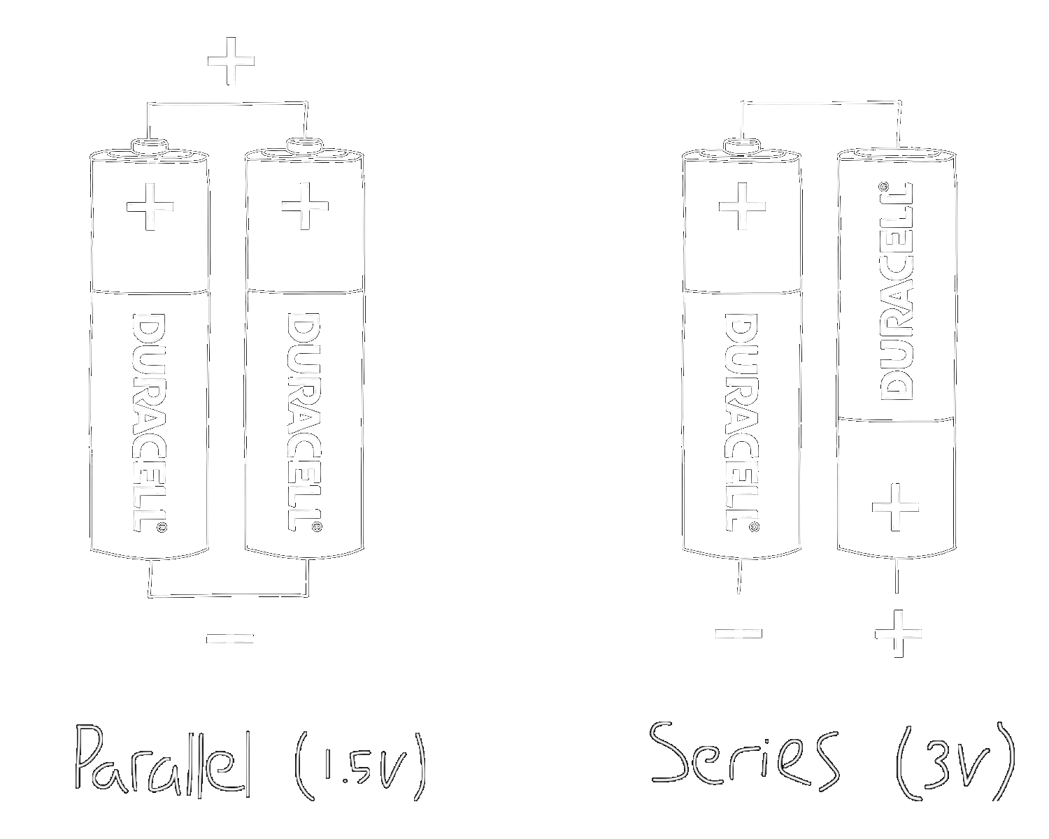
When replacing AA batteries, it's essential to ensure that the voltage is set correctly. This can be determined by measuring the voltage of the output wires from the battery compartment or inspecting whether the batteries are connected in series or parallel. In the case of a series connection, the voltage is the sum of the batteries, and in parallel, it is the same as one battery (in the case of AA or AAA, the voltage is 1.5V).
Here is an example of how I used this setup to replace the batteries in an LED light that required 3V.

Programming the USB-C Module
Connect your USB-PD trigger module to a USB-PD capable power supply using the USB-C connector. These modules provide you with different voltage modes, which are indicated by the LED. The mode can be changed by pressing the button.
- Red: 5V
- Yellow: 9V
- Green: 12V
- Light Blue: 15V
- Dark Blue: 20V
To set the modes as default, first plug the board into your power supply while holding down the button on the board. The LED will start flashing colourfully. Select the desired mode using the button. Press and hold the button to confirm your selection. Finally, disconnect the power supply from the module and then reconnect it so that the module now starts directly in this mode.
For detailed instructions, refer to the instruction manual.
Conclusion
By using a buck converter with a USB-C power delivery breakout board, it's possible to provide continuous power to devices that typically rely on batteries. This setup is flexible, allowing for voltage adjustments and providing a stable power source up to 3A. This method is particularly useful in applications where consistent power is expected, but the device expects batteries. I have used this setup to power my camera for extended periods which has allowed me to use it as a webcam.
--
Sindri Thor